I got the thing working but...
I actually got this thing working months ago, but didn't find the time to write the followup. Pics!
 |
| Testing the raspi camera and Movidius stick. I deleted lines of code from an example to get this to work. So easy! |
 |
| Not my finest work, but I was jamming at this point. |
 |
| A very capable board, for a very simple task. Overkill also brings expediency, I barely had to lift a finger to get the wireless connection going (after I settled on Modbus). |
 |
| The arrangement looking pretty good. |
 |
| Yah came together nicely. |
 |
| I bought this drill bit sometime ago. One of my favorite tools because it does the job so well. Figuring out where to land this hole was a delicate and careful process. I didn't want to ruin the sink. |
 |
| Faucet nicely installed. Very happy with how it turned out. |
I used a spare monitor to work on the pi locally, to get the camera right and set thresholds. I augmented the example I used to detect the cat with an on/off filter for the solenoid and a modbus library for connected to the ESP.
Here's the full test
... the battery runs out in a couple of days!!?
This thing was supposed to last for a month! What happened?
Turns out I didn't really understand the ESP specifications. The low current mode I was basing my design around disables the wifi transceiver which makes this somewhat useless for the cat. Really the ESP gives me an easy wireless interface to the solenoid control, and that's it.
Using Deep Sleep with an Interrupt
I need to get the standby current consumption of the solenoid controller down to miliamps. 5mA would be great, and get me nearly all the way to the goal of a month between charges.
My solution is to use a simple transmitter/receiver pair from the Sparkfun catalog to toggle a ultra-low-current watchdog chip typically used to reset microcontrollers, to reset the microcontroller (ie. wake it up) when the Pi sees a cat. From there we keep the controller alive by toggling the modbus coil. When the cat is finished and the Pi no longer sees a cat, the toggling stops and the controller goes back to sleep.

Of course there are some complications.
The radio works, pretty well...
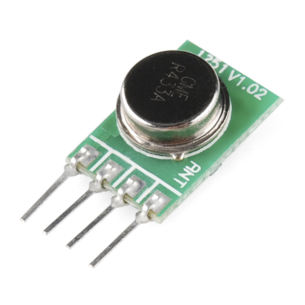
This is the radio:
Transmitter
https://www.sparkfun.com/products/10535
Receiver
https://www.sparkfun.com/products/10533
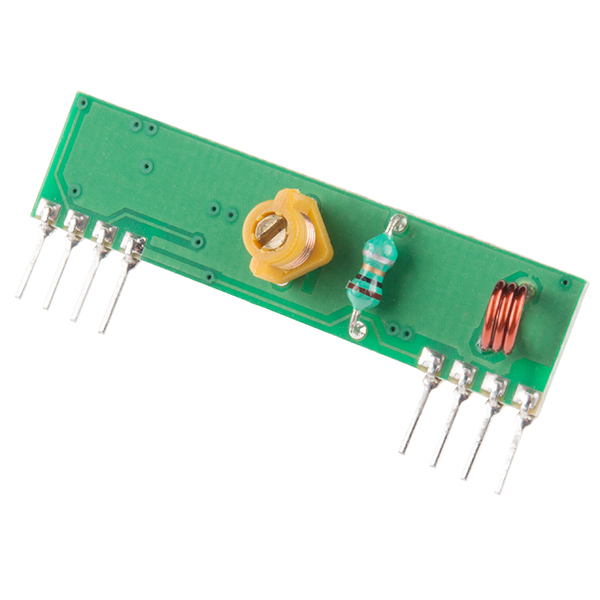
These little radios are handy. Very low current consumption, around 4.5mA (if I am reading the spec-sheet correctly). They provide a single channel, on-off, so essentially a serial interface. They have a drawback though... When the channel is quiescent, they are very noisy. The trick to using these things is to either discard the first few pulses as a kind of preamble, or to always be transmitting a pulse. 10Hz was the lowest frequency I tried that seemed to keep the noise away.
Watchdog circuit
555 chips can be used to create a watchdog circuit, but they actually consume a fair amount of current, 10mA typically. Nowadays you can find a very very low current watchdog chip typically used for microcontroller applications. I selected the UCC3946. It consumes up to 18uA. Nothing to blush at. I selected a timing capacitor to set the WD period to 10ms.
Proper toggling
To wake the chip up I just need to slow my GPIO toggle period to 10Hz. To keep the controller in whatever state it's currently in, asleep or awake, I just toggle it at 100Hz or faster.
More efficient solenoid driver
During the time when this was working...somewhat I started on a sprinkler controller and started learning more about solenoid driver circuits. Obviously with a sprinkler controller, especially one running on a battery, you want power efficiency wherever you can manage it.
Spike and hold
Spike and hold uses a voltage spike to open the solenoid and a lower voltage to keep the solenoid open. So I can lower the power consumption of the solenoid driver by using such a circuit. I used a network analyzer to figure out the inductance and series resistance of the solenoid and designed a spike and hold circuit like the ones described here.
Conclusion
I learned a lot about these ESP chips, and their low power modes. From here I am wrapping up some modifications to the code to use the radio and we'll see if this works better. Here's a picture of the new design!
