Where we were
So I had just finished a quick test with some foil to see if the idea of painting the drawers would serve to turn them into an effective light tube. It worked. I had also bought the LEDs and the driver chips. I made a proto-board version of the backplane, and that sucked, so I knew I needed to find a better solution. Enter Halted Electronics.
The backplane and mounting
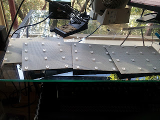
So I found this awesome proto-board at Halted that was basically tinned copper clad on one side, with predrilled holes in it (just like regular protoboard). I mapped out on the boards where the LEDs would sit and cut out some isolated areas on the board. I forget if the rest of the board was Vcc or Gnd... Then all I had to do was solder the LEDs, and the connector, and run wire back to the connector. The other LED legs were all on a common plane.


And, yes, it took a couple of weekends to do.
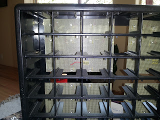
For mounting the board to the drawer holder I just made sure to line them up a bit and drilled a hole in the back. Then I used a couple of regular screws and a screw driver and fixed them to the back.


Painting the drawers
Probably the longest and most arduous task in this project. To assist in the process I started out using these pieces of cardboard, but that was too slow. I ended up just using masking tape and spending a few hours taping up all the drawers. 64 drawers later I had them all painted. Then it was time to do it again!


LED Drivers and whatnot
As discussed previously the LEDs are driven using the TLC5940. My prototype uses 4 of them, one for each board, and an arduino to control them. Most of the software was already written so I designed a PCB and sent it out to the board house.


Software
Once all of the wires were soldered, and the boards populated I went about mapping the LEDs in the Arduino. With a properly mapped LED matrix I was able to start working on the screensaver. One really neat thing about this box system is that it's also great for parties.
I wanted to have the drawers light up along with music from my computer. Being that I like to do things the hard way I decided that it would be awesome to have the computer stream the results of a Fourier transform done in soft real-time. After searching around on the internet for a while I found a visualizer that I could easily hack to suit my needs.
Impulse is a simple music visualizer for Ubuntu that looks good by itself. I liked it because it was already set up to interface with Pulseaudio. Pulseaudio is an audio software layer in Ubuntu, which has the nice feature of automatically creating a soft channel monitor for every output stream it handles. This is the software output monitor that Impulse uses to pass the audio stream to its FFT. From there it was a simple matter of importing impulse, calling the function, and massaging the output into my array -> serial protocol -> serial com link to the arduino(child's play in python).
Once I had the array in the arduino (the array is basically 8 numbers that represent the energy in each frequency band) it was straightforward to control the LEDs.
One issue that I had/have was timeout. Sometimes the serial link will have too much information passed down it. One symptom was that the device would simply quit working. To fix this I increased the baud rate, and turned on the watchdog feature for the arduino. Now if the arduino hangs because of serial issues, the watchdog will notice and restart the arduino. Here's more info on the watchdog features of the arduino: Arduino Watchdog.
I also had to do some tweaking to have the equalizer be more 'active'. Here's a video of what the system behaved like before the tweaking: pre-tweak.
After working with it a bit, this is what I have...
So what's next?
I have some time tonight. With the Maker Faire coming up on Sunday I am reminded that I have a bunch of pretty cool ideas backed up right now because I haven't finished this thing. Motivation is at an all time high, so I think I'll try and ride the wave all the way back into shore. First thing is first. I will need to finish development of my parts database. I want to have a good interface that will allow me to quickly add parts, reorganize the drawers, keep track of quantity, etc... I consider this step done when I have the database somewhat populated, I can complete searches using simple phrases like "1.uF," and the result will be returned via a lit up drawer.
After that is completed (I think about a week or so), I want to start making my android app. The android app is where I'll get voice search capabilities from.
As a final stroke I will also include a feature that will allow a user to build a BoM and have the system automatically light up drawers so that parts can be retrieved all at once. Additionally this thing will alert you when you run low on a part so you'll know to buy more.