Sunday, February 10, 2019

CAP Water Fountain Power Consumption Limbo

Update

Since the last post I have been working a lot to continue to bring my current consumption below 1mA. My last post set the target to 5mA in standby, but first, that technically falls short of my original goal and second it's optimistic. I am not sure the battery actually has that capacity. Getting below 1mA is really tricky and it took a fair amount of scouring the internet for a solution. I actually managed to find a couple of solutions, and I've been running tests on one of them while I finish the design of the second.

Upfront disclosure: I am not going to reveal what I found just yet, as I want to be able to sell the solution first when I eventually give away all the details.


Leaks

As I ran lifetime tests, monitoring the battery voltage, I realized I had a leaky ship. Just looking at the above image you can see some of the issues, hint, they are bright.
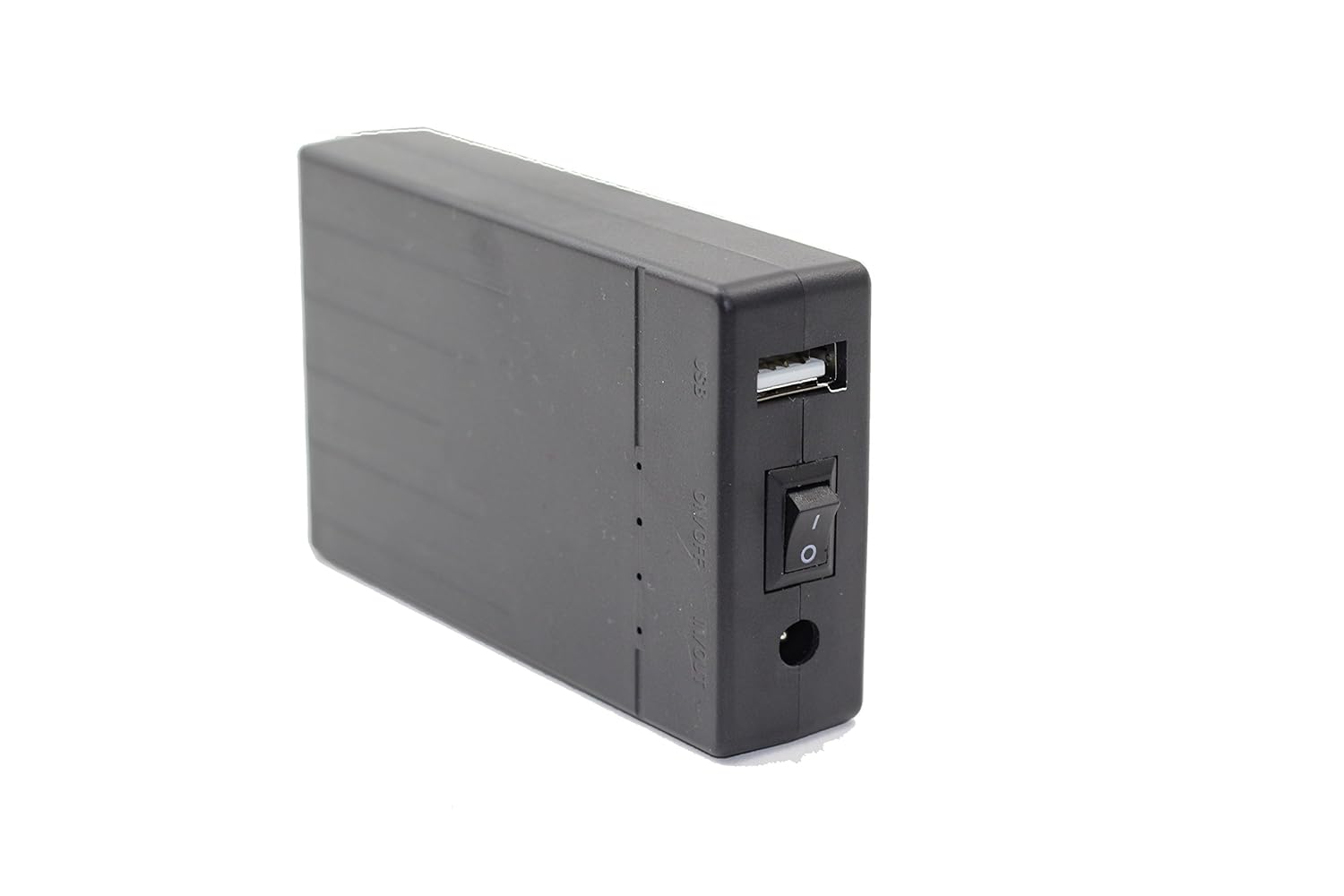
The battery

First thing was the battery itself. There were two power consumers in the battery which meant the battery alone wouldn't even stay on without a load for more than a week or so. There are LEDs to indicate the level, and circuitry to measure the voltage and light the LEDs, and an inefficient (by this project's needs) linear regulator supplying the USB 5V (the battery is 12V). Instead of buying a new battery pack, I ripped this one open, disabled the LED status circuits (ripped up traces), and the regulator circuits. I left the battery management board in-place as it seemed to have a large diode in the way of it affecting standby draw.

I replaced the battery built-in regulator with a low quiescent current regulator on my board to convert the 12V to 5 for the thing-dev. (MCP1702)

With all of the extra junk from the battery gone, I ran another test with just the battery and it looks like there's still something eating the juice, but it's negligible for now.

Thing Dev

I ripped up the LED traces from the board, as they consume a nice ~5mA.

Conclusions and next steps

I made some progress reducing current consumption in the design, and this has extended the standby to 20+ days. But this can be improved further. I also realized some time ago I need to directly measure the current consumption, so I've been looking into the best way to do that.

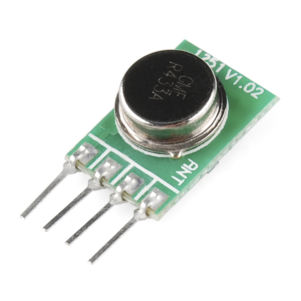
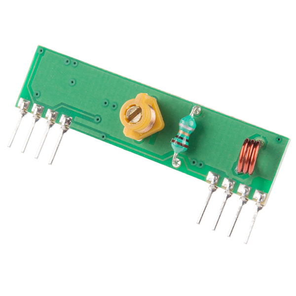
Also, my venture has highlighted a bit of a hole in the realm of wake-up-receivers for ESPs and other IoT things. I think I can put together a board that will plug into the Thing Dev and enable wireless wakeup from a Pi for a close and medium range application. I figure I can't be the first person to wish for such a board. So I've been working on a design and I plan to order the PCB and make a first-article in the next month or so. Hopefully the short and medium range approach both pan out...

Thursday, July 5, 2018

CAP - Water Fountain Power Consumption Issues

I got the thing working but...

I actually got this thing working months ago, but didn't find the time to write the followup. Pics!
Testing the raspi camera and Movidius stick. I deleted lines of code from an example to get this to work. So easy!

Not my finest work, but I was jamming at this point.

A very capable board, for a very simple task. Overkill also brings expediency, I barely had to lift a finger to get the wireless connection going (after I settled on Modbus).

The arrangement looking pretty good.

Yah came together nicely.

I bought this drill bit sometime ago. One of my favorite tools because it does the job so well. Figuring out where to land this hole was a delicate and careful process. I didn't want to ruin the sink.

Faucet nicely installed. Very happy with how it turned out.


I used a spare monitor to work on the pi locally, to get the camera right and set thresholds. I augmented the example I used to detect the cat with an on/off filter for the solenoid and a modbus library for connected to the ESP.


Here's the full test


... the battery runs out in a couple of days!!?

This thing was supposed to last for a month! What happened?

Turns out I didn't really understand the ESP specifications. The low current mode I was basing my design around disables the wifi transceiver which makes this somewhat useless for the cat. Really the ESP gives me an easy wireless interface to the solenoid control, and that's it.

Using Deep Sleep with an Interrupt

I need to get the standby current consumption of the solenoid controller down to miliamps. 5mA would be great, and get me nearly all the way to the goal of a month between charges.
My solution is to use a simple transmitter/receiver pair from the Sparkfun catalog to toggle a ultra-low-current watchdog chip typically used to reset microcontrollers, to reset the microcontroller (ie. wake it up) when the Pi sees a cat. From there we keep the controller alive by toggling the modbus coil. When the cat is finished and the Pi no longer sees a cat, the toggling stops and the controller goes back to sleep.


Of course there are some complications.

The radio works, pretty well...

This is the radio:
Transmitter
https://www.sparkfun.com/products/10535


Receiver
https://www.sparkfun.com/products/10533


These little radios are handy. Very low current consumption, around 4.5mA (if I am reading the spec-sheet correctly). They provide a single channel, on-off, so essentially a serial interface. They have a drawback though... When the channel is quiescent, they are very noisy. The trick to using these things is to either discard the first few pulses as a kind of preamble, or to always be transmitting a pulse. 10Hz was the lowest frequency I tried that seemed to keep the noise away.

Watchdog circuit

555 chips can be used to create a watchdog circuit, but they actually consume a fair amount of current, 10mA typically. Nowadays you can find a very very low current watchdog chip typically used for microcontroller applications. I selected the UCC3946. It consumes up to 18uA. Nothing to blush at. I selected a timing capacitor to set the WD period to 10ms.

Proper toggling

To wake the chip up I just need to slow my GPIO toggle period to 10Hz. To keep the controller in whatever state it's currently in, asleep or awake, I just toggle it at 100Hz or faster.

More efficient solenoid driver

During the time when this was working...somewhat I started on a sprinkler controller and started learning more about solenoid driver circuits. Obviously with a sprinkler controller, especially one running on a battery, you want power efficiency wherever you can manage it.

Spike and hold

Spike and hold uses a voltage spike to open the solenoid and a lower voltage to keep the solenoid open. So I can lower the power consumption of the solenoid driver by using such a circuit. I used a network analyzer to figure out the inductance and series resistance of the solenoid and designed a spike and hold circuit like the ones described here.

Conclusion

I learned a lot about these ESP chips, and their low power modes. From here I am wrapping up some modifications to the code to use the radio and we'll see if this works better. Here's a picture of the new design!

Tuesday, March 20, 2018

CAP - Water Fountain: Engineering

Intro

My cat only drinks from the tap. He doesn't know how to turn the water on or off. So I need a system to get him water when he wants it.

Requirements

  • Need
    • Clean install
    • Provide water when cat goes to the sink
      • Don't trigger on humans
    • Turn water off when cat is done
    • Run for a month between charges
  • Want
    • Tweet/ notify when cat gets water for peace of mind
    • Notify on low battery
    • Easily integrated and removed

Engineering

Clean install

I picked a sink I can easily modify to include a spout, and he's used to drinking from. There is no outlet nearby that I can wire to cleanly. So I'll have to use a battery.

A clean install means no visible wires or tubes running through the sink. 

Provide water: turn off/on when cat comes around

Control

ESP 8266 Thing from Sparkfun promises low-current draw and WiFi, nice!

Actuation

Use a solenoid valve:
DIGITEN DC 12V 1/4" Inlet Feed Water Solenoid Valve Quick Connect N/C normally Closed no Water Pressure

Sensing

Sensor selection/ design will be a trade off between accuracy and visibility.

IR sensor

  • Pros
    • Pretty standard way of doing automatic sinks
    • Cheap sensors
  • Cons
    • Wires
    • Very visible sensor
    • Compact or clean looking versions are hard to find ($$)
    • Might trigger when I'm using the sink (not desired)

Capacitive something...

  • Pros
    • Clever sensor placement/ design could exclude everything but the cat
    • Minimal
  • Cons
    • Might be visible
    • Not really straightforward

Piezo loadcell

  • Pros
    • Minimal, very clean, invisible
  • Cons
    • Difficult to design against non-cat triggers (extra weight in the sink will cause it to fire)

Machine vision

  • Pros
    • Fun to make
    • Could become very good at cat-only triggering
  • Cons
    • Overkill
    • Visible sensor/ camera

Run for a month between charges

Add up all the current consumers and estimate Oppie's drinking habits. Pretty simple.

  • ESP8266
  • Awake: ~200mA
  • Standby: ~0.9mA
  • Solenoid valve ~ 400mA

Oppie drinks water for ~ 10 minutes a day. 31 days in a month = 310 minutes.

I picked this thing:

The ESP may actually consume less current while running, but assuming some leakages here and there keeps things conservative.

Conclusions

  • Control and actuation is pretty straightforward. No decisions.
  • Battery pack looks like it should be sufficient
  • I'll use machine vision to detect the cat. Especially considering how cool/easy this thing looks:
Image result for intel movidius
Plus the fact that I can get this to trigger only on cats is really neat.


Sunday, January 7, 2018

Timber Spider

Getting there first

My parents are part of a timeshare pool in which they can trade weeks at their location for weeks at other places in the pool. Weeks are submitted to the pool by other owners, at semi-random, and are reserved on a first-come-first-serve basis. Some places are reserved more quickly than others. My dad checks the website that lists the locations almost every day. I thought... why not every hour? It was decided to send an MMS any time a really good week was added, and an email anytime a week of any quality was added or removed. Hopefully by getting alerts sent to our phones we could secure our favorite weeks before anyone else.

Making a robospider

After a few iterations I decided that scrapy was the right tool. It has a lot of stackoverflow stuff, a bunch of automation, processing pipelines, etc.
The availability website is behind a password protected login so I needed to use a spider that could handle the authentication step. I decided to use the InitSpider as it handles authentication before crawling.
Next I told the spider to seek out the "next >" links on the page for creating followup requests. The availabilities are listed in a standard table, so I parse each row as a scrapy Item. I set up an item processing pipeline and activated it to do the alerting.

Alert system

Items gleaned by the spider are passed through a pipeline which assembles them into a dictionary and compares them to an older dictionary for a difference. The older dictionary is shelved when the spider is closed. I decided to shelve the dictionaries as it seemed really easy to do and I thought doing something like a JSON export was overkill. Turns out shelving is really easy (except when it's not).
The comparison creates three lists: additional really good weeks, new weeks, and removed weeks. Later in the pipeline the text message and email is formatted. Both required setup of a dummy gmail account to send to my family. 

Installing and Automating

I had to get scrapy installed in a conda environment (turned out to be a problem) on my pi. I made sure to install the following before attempting to install scrapy.
sudo apt-get install libffi-dev
sudo apt-get install libxml2-dev
sudo apt-get install libxslt1-dev
sudo apt-get install python-dev

It took a while for lxml to build on my little pi (~20 minutes). But after that step scrapy seemed to be available. I loaded my spider and hit go and ran smack into my first issue.

Traceback (most recent call last):
  File "/home/pi/berryconda2/lib/python2.7/site-packages/twisted/internet/defer.py", line 1386, in _inlineCallbacks
    result = g.send(result)
  File "/home/pi/berryconda2/lib/python2.7/site-packages/scrapy/crawler.py", line 98, in crawl
    six.reraise(*exc_info)
  File "/home/pi/berryconda2/lib/python2.7/site-packages/scrapy/crawler.py", line 82, in crawl
    yield self.engine.open_spider(self.spider, start_requests)
ImportError: No module named _bsddb

OK so I gotta figure out what this bsddb thing is. Apparently it's some BerkelyDB interface that twisted appears to use.

Getting bsddb3

First thing was to get the BerkeleyDB built for my pi. I followed the install instructions here:

Make sure you install the older version of BDB (5.3.28)

Actually I tried to just pip install bsddb3 but got smacked down.

After a while I decided to drop shelve, as soon as it seemed like it might be causing the bsddb dependency. After dropping it I encountered a new error, ECC Curve.

I went to the Twisted IRC after bashing my skull against the problem for a while and someone confirmed there was some missing stuff from my pyopenssl build. They said they'd try and reproduce the issue. So I waited for a bit.

Forgetting bsddb3, something else is wrong

I tried updating cryptography, twisted, and pyopenssl to the most recent versions I could. I did everything short of updating openssl for the pi to 1.1 (I am was running Jessie). Nothing seemed to work. So I hopped into the IRC for twisted and got some help from runciter. After running some tests they concluded conda was my problem. Specifically berryconda and my old openssl libs. I need to bump to 1.1 but I couldn't easily do that with Jessie. So I decided to upgrade to Stretch. After upgrading to Stretch and uninstalling scrapy, twisted, pyopenssl, and cryptography I installed scrapy again and voila, it works.

Wrapping it up

Last step was to add a simple cron job to execute my script on the hour from 6-23. 

Friday, January 5, 2018

Electronic Component Organizer Android App and Other Progress

On a roll

Lately I've taken it upon myself to really try and push to get this project done. It's been over a year or two in the making and I need to finish it. Unfortunately I keep getting sidetracked by extra things I want to do with it.

For instance, this week I had the idea of using my fancy new bluetooth receiver to serve as the wireless connection to the component organizer. I found some cool projects that people have worked on that provide ways to transfer data from an Android phone to an Arduino using FSK over the audio port (with music as the carrier?). 

So after a quick shopping spree at SF, I have some new toys shipping to me presently. My idea will be to do a pass-thru of the audio signal from the bluetooth receiver, through an Arduino based "box." This box will use an Arduino (or PIC?) to process the signal, and send the results to the box system via 315MHz radio. The results will either be an audio waveform FFT, or the address of a part. So when the box is idle the screen saver will be the FFT of the music passing through the receiver. If an address is requested, the request will be passed via FSK to the "analyzer" and then passed to the organizer.

And just when I thought I was finally finishing this thing...

Django Database and Dajaxice

I did manage to get my Django system running pretty much how I want. I am lazy and didn't want to build my own views for Django when the admin views were all I would ever need, and look so good. So I set to learning about how to modify the Django admin site (extend is the technical word). The framework is pretty easy to deal with. I managed to an ajax based button inside the change_list_results list. And through a bit of hacking managed to get that button to open a serial connection to the organizer Arduino, and send the address of the part. Once that system was running smoothly, I set about organizing my resistors.


Two movies (The Hobbit and There Will Be Blood), and a bunch nachos later and I finally have all my resistors organized. That's not to say I have all the standard 5% resistors in this box system (that would be too many even with each drawer divided into 2), but all the ones I do have are now organized. I don't have to wonder if I have any given resistor because I have then all inventoried.

Looking back, I feel like this project has been one of the most tedious I have ever undertaken. It is taking a lot of will power to not give up until every last resistor I own is properly organized. I mean... I think I went kinda crazy there for a while. Who pays that much attention to their resistor collection? I'm just glad I got it over with...

Android Studio, and Ubuntu 64bit

The next phase of this project is to get the voice search functioning. I am going to use my Android phone for the approach. The idea is to write an app that will use google's speech input API to interpret my speech. Then using tags for each entry, some manually entered, some automatically associated based on component data, search the database for the part. Once a part or list of possible parts is found, provide a "light it up" button that shows where the part is located. Upon clicking the button an address request is sent via the audio connection over bluetooth to the receiver. On it's way out of the bluetooth receiver the audio signal is picked up by the Arduino receiver which is programmed to recognize the FSK message. It relays the address via 315MHz radio to the orgranizer which then lights up the box.

Getting the app ready starts with learning how to write apps for Android, and getting my IDE all set up. I chose to go with Android Studio, because Google's IO conference debut of the IDE looked amazing.

After downloading and "installing" I started it up and started working through a tutorial on the speech recognition API. Android studio has this nice auto compile feature that tells you if your code works. When my setup tried to compile I ran into some issues which I posted, then solved, here.


Monday, September 2, 2013

Django, Dajax, and Getting Dajax to work (Lite-Em-Up Component Organizer)

Django

After futzing around with all sorts of database application approaches, I finally settled with Django. Here's what I messed with:
  1. Pure sqlite implementation with python application for interface
  2. MS Access Database
  3. Finally, Django
The pure approach at the top is probably what I'd end up going for if I ever wanted to mass produce this, MS Access was painful and nearly useless (it was a dark time in my life). Django has offered the easiest database creation/ application development framework of all three. So it was very attractive for my "just get it done" state of mind. Not only that but most of the interface for working on the database contents has already been made for you (in the admin site). The only thing left for me was figuring out how I was going to use the nice interface to make a box light up... a button perhaps? A button that could run a python script. The tricky part is how do you wire up the button which is in a webpage that Django serves, to run your dead simple python script? And how do you pass the script the number of the box to light up?

The answer is of course, Dajax. Not only will dajax serve me well for this project, but also for all the other projects I have going at work to create database systems for control component management and planning.

Dajax

Starting from here, I was able to gather that this dajax thing was pretty powerful, and handy. But the example leaves a lot out. I tried going through the setup documentation, but it is also operating from the assumption that you pretty much know what you're doing... Not only that, but there are almost no very basic tutorials for the current (0.9 dajax, 1.5 django) releases. So that's what I am going to write here, somewhat for you, and mostly for me.

How to get a button on a django webpage to execute a python script using dajax:

This tutorial assumes that you already have Django 1.5 setup. I do not claim to be any sort of an expert, my training was in mechatronics and physics, so getting Django to work for me has been an exercise in hacking all the way. That being said, here we go!

Dajax Setup

First install dajax and dajaxice using pip.
 sudo pip install django_dajax  

Then follow these instructions to add dajaxice to your project (required!). Some points for clarification: the urls.py to add your dajaxice url to is for the site (not the app!). You probably could have figured that out, but just to save you some questioning.

Finished? Great! Now follow these instructions to install dajax. For clarification this is what I did for the jquery step ( I was confused because I thought you simply add this line to your head:
 {% static "/static/dajax/jquery.dajax.core.js" %}  
 but you need to embed it sensibly like so:
 <script type="text/javascript" src="{% static "/static/dajax/jquery.dajax.core.js" %}"></scrip>  
t>

Also make sure you load the staticfiles lib into the template (place this at the top of the template):
 {% load staticfiles %}  

The meat

Here's my template page all together:
 {% load dajaxice_templatetags %}  
 {% load staticfiles %}  
 <head>  
 <script type="text/javascript" src="{% static "/static/dajax/jquery.dajax.core.js" %}"></script>  
 <script type="text/javascript" src="{% static "/static/eci/jquery-2.0.3.js" %}"></script>  
 {% dajaxice_js_import %}  
 </head>  
 <button onclick="Dajaxice.eci.light_up_box(Dajax.process);">Show me where</button>  

A few things to note:

  • I downloaded the newest jquery from the jquery website here, and placed it in the app folder under static/eci/ where eci is the name of my django app.
  • The onclick call goes as Dajaxice.appname.function in the ajax.py.
Here's my ajax.py code which resides in my app folder (called eci in my case, for electronics component inventory):

 from dajax.core import Dajax  
 from dajaxice.decorators import dajaxice_register  
 import serial, time  
 @dajaxice_register  
 def light_up_box(req):  
   dajax = Dajax()  
   dajax.alert("Hello World!")  
   serial_port = serial.Serial('/dev/ttyUSB0', 9600, timeout=None)  
   box_number = 4  
   number = str(box_number)  
   if box_number <10:  
     number = '0'+number+'X'  
   else:  
     number = number+'X'  
   serial_port.write(number.strip())  
   serial_port.close()  
   return dajax.json()  

I use the dajax.alert function to confirm independently that the dajax function was called. I'll probably use it later to confirm that the box was found and the part removed (ask for a quantity or something).

That's the long and short of it. I hope it helps you. I was really sad when I couldn't find a basic tutorial that explained the stupid questions I had, hopefully you don't have the same problem!

Wrap up

So as of last night the electronics component organizer has been improved a bit. I have a larger current power supply connected, which will hopefully help with the power issues I've been having. I have also finally secured my pcbs and power supply to the top of the box so it's not so janky. Also, now that I have this dajax thing working I can finally start putting together the rest of the database viewing pages that will allow me to light up boxes at will.

Thoughts for the future:

I think I might have made a mistake trying to get my computer to stream the FFT data to the arduino over serial. I may end up making a new pcb that has an audio jack pass through so that the FFT can be done directly on the arduino. Once the basic database is done I'll probably go ahead and populate the organizer with parts. That will probably take a good part of a Saturday.

Thursday, May 16, 2013

Lite-It-Up Component Organizer.

So it's been a long time. Actually over a year since I last posted about this project. There has been progress. Unfortunately for the past several months it's kind of been on the backburner. Between working on my house, working at SLAC, and nailing down my rhythm I haven't had mad this project a high priority. Hopefully the blog post means that will change soon. Enough words, let's get down to what's happened.

Where we were

So I had just finished a quick test with some foil to see if the idea of painting the drawers would serve to turn them into an effective light tube. It worked. I had also bought the LEDs and the driver chips. I made a proto-board version of the backplane, and that sucked, so I knew I needed to find a better solution. Enter Halted Electronics.

The backplane and mounting

So I found this awesome proto-board at Halted that was basically tinned copper clad on one side, with predrilled holes in it (just like regular protoboard). I mapped out on the boards where the LEDs would sit and cut out some isolated areas on the board. I forget if the rest of the board was Vcc or Gnd... Then all I had to do was solder the LEDs, and the connector, and run wire back to the connector. The other LED legs were all on a common plane.


And, yes, it took a couple of weekends to do.

For mounting the board to the drawer holder I just made sure to line them up a bit and drilled a hole in the back. Then I used a couple of regular screws and a screw driver and fixed them to the back.


Painting the drawers

Probably the longest and most arduous task in this project. To assist in the process I started out using these pieces of cardboard, but that was too slow. I ended up just using masking tape and spending a few hours taping up all the drawers. 64 drawers later I had them all painted. Then it was time to do it again!


LED Drivers and whatnot

As discussed previously the LEDs are driven using the TLC5940. My prototype uses 4 of them, one for each board, and an arduino to control them. Most of the software was already written so I designed a PCB and sent it out to the board house.


Software

Once all of the wires were soldered, and the boards populated I went about mapping the LEDs in the Arduino. With a properly mapped LED matrix I was able to start working on the screensaver. One really neat thing about this box system is that it's also great for parties.
I wanted to have the drawers light up along with music from my computer. Being that I like to do things the hard way I decided that it would be awesome to have the computer stream the results of a Fourier transform done in soft real-time. After searching around on the internet for a while I found a visualizer that I could easily hack to suit my needs. 
Impulse is a simple music visualizer for Ubuntu that looks good by itself. I liked it because it was already set up to interface with Pulseaudio. Pulseaudio is an audio software layer in Ubuntu, which has the nice feature of automatically creating a soft channel monitor for every output stream it handles. This is the software output monitor that Impulse uses to pass the audio stream to its FFT. From there it was a simple matter of importing impulse, calling the function, and massaging the output into my array -> serial protocol -> serial com link to the arduino(child's play in python).
Once I had the array in the arduino (the array is basically 8 numbers that represent the energy in each frequency band) it was straightforward to control the LEDs.

One issue that I had/have was timeout. Sometimes the serial link will have too much information passed down it. One symptom was that the device would simply quit working. To fix this I increased the baud rate, and turned on the watchdog feature for the arduino. Now if the arduino hangs because of serial issues, the watchdog will notice and restart the arduino. Here's more info on the watchdog features of the arduino: Arduino Watchdog.

I also had to do some tweaking to have the equalizer be more 'active'. Here's a video of what the system behaved like before the tweaking: pre-tweak.

After working with it a bit, this is what I have...


So what's next?

I have some time tonight. With the Maker Faire coming up on Sunday I am reminded that I have a bunch of pretty cool ideas backed up right now because I haven't finished this thing. Motivation is at an all time high, so I think I'll try and ride the wave all the way back into shore. First thing is first. I will need to finish development of my parts database. I want to have a good interface that will allow me to quickly add parts, reorganize the drawers, keep track of quantity, etc... I consider this step done when I have the database somewhat populated, I can complete searches using simple phrases like "1.uF," and the result will be returned via a lit up drawer.

After that is completed (I think about a week or so), I want to start making my android app. The android app is where I'll get voice search capabilities from. 

As a final stroke I will also include a feature that will allow a user to build a BoM and have the system automatically light up drawers so that parts can be retrieved all at once. Additionally this thing will alert you when you run low on a part so you'll know to buy more.